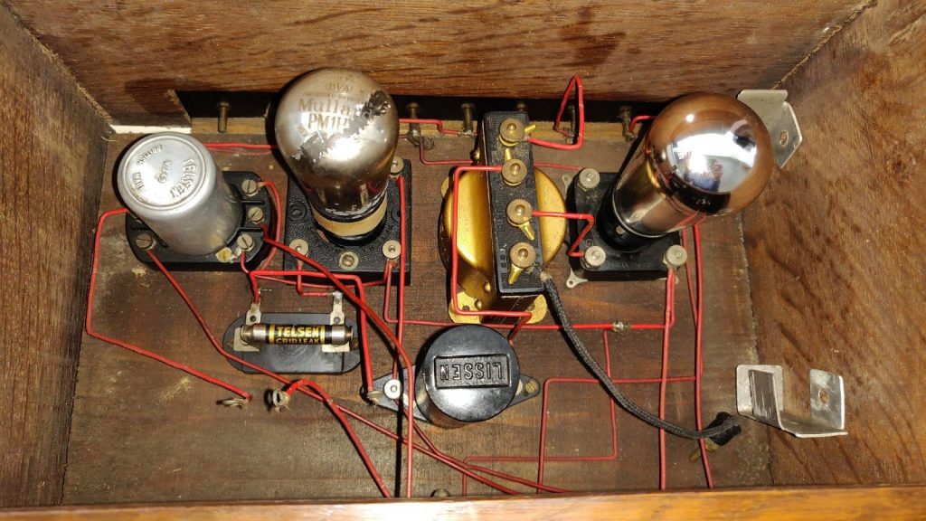
Whilst looking around for a 1920s style radio, I found this old thing on eBay. It looked nothing like a commercial set, using rigid interconnecting wires and screw terminals between internal components. I was captivated by the simplicity of it. As is was missing a critical component, the tuning capacitor, it wasn’t very expensive so I bought it immediately.
It sat on my shelf for nearly a year before I had the time to concentrate on it. Recently, with a virus caused lock-down in place, I took it down from the shelf and had a look at the components in there. It didn’t look like there was enough to make a fully working radio.
Looking at the manufacturer markings on the components, the name Telsen stood out, so I did a little bit of Googling, and found the Telsen radio magazines here:- http://telsen-radiomag.uk/
It seems that Telsen were producing components for the home radio constructor, and what I had here was a home made radio set. These magazines are a great snapshot of a past time and I owe a debt of gratitude to David Andrews for making these available. Each issue would detail the circuit diagram and blueprint for construction of several types of radio set.
So, after an interesting read through all of the editions of this magazine, I found that none quite matched what was inside of this 90 year old wooden box. The closest design they had was the ‘Songster 2’ in the first issue, but that design used an earlier type of aerial coil.
After reverse engineering the radio to a circuit diagram, I could see that it was a similar circuit to the songster 2, and would use the notes in that magazine article to help me along.

With some use of a basic multi-meter, I was able to determine that all the aerial coil was good, as was the RFC chock and inter-valve transformer. The heaters on the two valves were good too, but the 2 meg-ohm grid leak resistor was bad, I was able to repair this by opening it and soldering inside a couple of one meg ohm resistors in series.
This type of radio needs a grid bias battery to provide a negative bias voltage for the audio amplifier valve. Given the provision was already made inside the box for such a battery, I created my own little one using cardboard, AAA cells and an only plug socket board.

A 2 volt heater supply was required for the valves. Fortunately, small 4Ah lead acid cells are available from model hobby suppliers.
A HT supply is also required, usually about 60 volts for the RF valve and 80 volts for the audio amplifier tube. This was created using a 9 PP3 9 volt batteries in series with a tap at 63 volts.
The audio output terminals needed to be connected to a high impedance load, so for testing purposes, I connected up a speaker transformer with a regular 8 ohm speaker.
With everything done, I was keen to see if there was any life in this thing. I connected up a tuning capacitor salvaged from elsewhere and gave it a try. So to my surprise, there was life in it. Lots of noise and howling from the regen. With some adjustment, I was able to pick up radio 4 on LW, but nothing on MW.

Happy that the radio was fundamentally workable, I set about looking around for a vintage single gang tuning capacitor that would fit in well. I found a great brass built Ormond tuning capacitor with fast and slow dials which fitted perfectly.

The final stage to this radio set was to find a suitable vintage external speaker. What I found was an art deco styled external speaker with a moving iron driver with paper cone. This seemed a perfect complement to the style and vintage of this radio set and the paring of those components can be seen below.

This video below demonstrates this radio in action


Leave a Reply