This Philco is a small cheap table top radio. It’s very simple in design, has quite a low component count and actually works really well. The only down-side to it’s design is that it uses a dropper-resistor to step down mains voltage to power the heaters in the valves. This is really inefficient, of the 43 Watts consumed by the radio, about 30 is burned up in that resistor! I guess it doubles as a nice personal heater for those cold winter nights!

The cabinet wasn’t too bad, just needed touching up in spaces, and fresh black surround. The speaker cloth was coming apart though, so standard vintage style cloth was used as a replacement. The tuning indicator was missing as was the cord that links it all together.

Only four valves in this set, valve technology must have really improved between the 40s and 50s because the output level and sensitivity of this set is excellent.
The usual tests procedures were carried out, test the power supply, replace any bad resistors (there were a few) replace or reform the power supply reservoir capacitors.

This set had all three of it’s power supply smoothing capacitors stored in the same aluminium can. I broke with the usual tradition of replacing them with modern electrolytic caps as a matter of course and spent some time reforming them using a special high voltage power supply and series resistance.
The theory goes with aluminium electrolytic caps is that their aluminium oxide insulating layer will return with a steady current at the working voltage of the capacitor. There is a formula of 55 minutes plus one minute for every year the capacitor has not been used. I repeated this with each of the three capacitors in that can and to my satisfaction, found it to have been a success.

After a couple of safety checks and a new mains lead install, I fired this up to see if it had any life in it, and almost instantly (after the tubes had warmed up) it was belting out sound.
I was quite impatient to put everything back together and test, any further work would require more parts to be ordered, as the knobs were partially missing and the tuning screen lost some of it’s translucent paint.
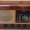
The video below shows the Philco working as a fully assembled set. It is possible to see that the tuning indicator is the shadow type and relies upon translucent paint on the back of the glass screen.
This post will be continued…

Leave a Reply