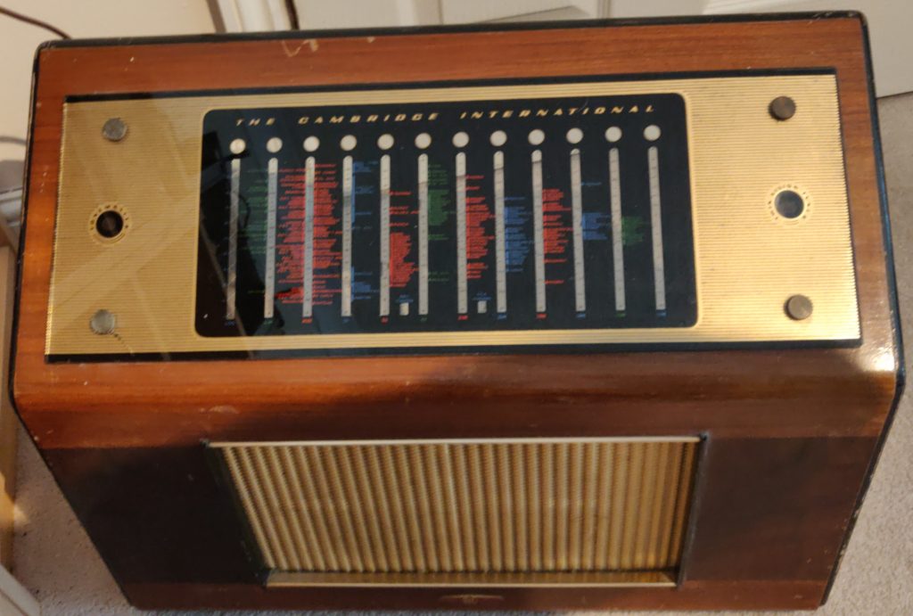
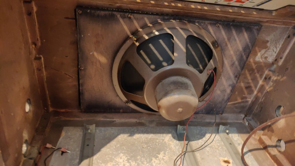
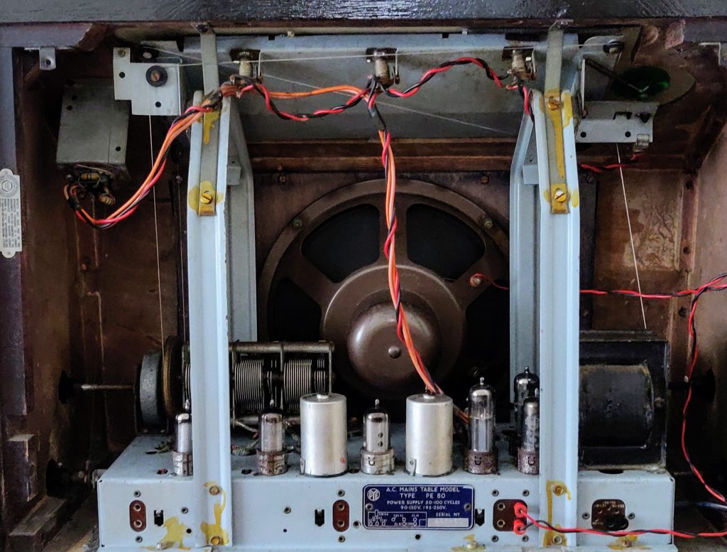
I was really lucky to be given one of these beauties. It a high end radio from the mid 1950s, with lots of SW bands, a front-end RF amplifier (most designs I’ve seen so far don’t use one) Push-Pull audio output valves, a magic eye tuning indicator and a big 10″ speaker.
I’m going to take my time with this one, it’s a bit of a beast and I want to enjoy restoring it as much as I’ll enjoy using it.
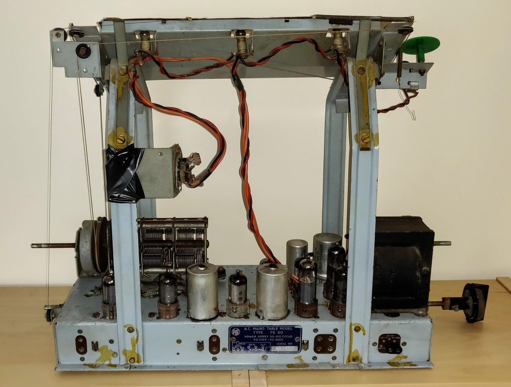
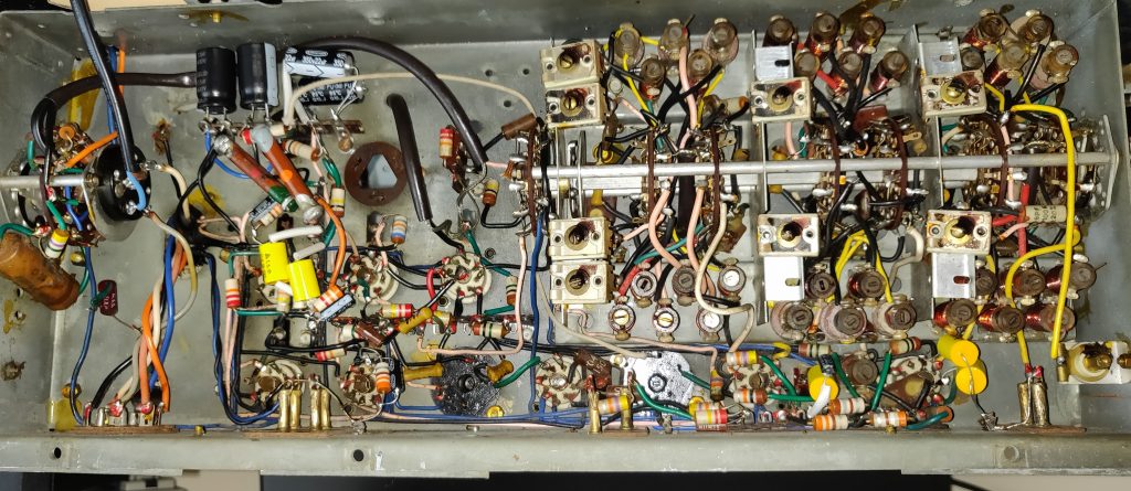
Like previous PYE designs, the chassis it quiet tidy, which represents it’s era of manufacture. Because of it’s specification, the power supply is a sophisticated design with two separate networks of RC filters. This has given me more to replace, so parts are on order.
I won’t be bothering with directly replacing the 32-32 and 16-16 dual capacitor cans as these are really difficult to find at the moment. I will add some vintage tag strip to the chassis and rewire it to use standard discrete power supply capacitors, below the deck.
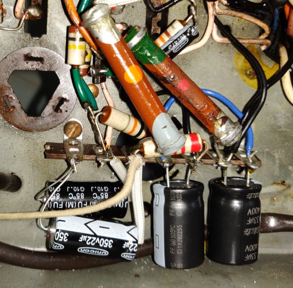
There are quite a few other capacitors that will need replacing. Fortunately, they’re not too difficult to get to. The image below shows the complete chassis with capacitors replaced.
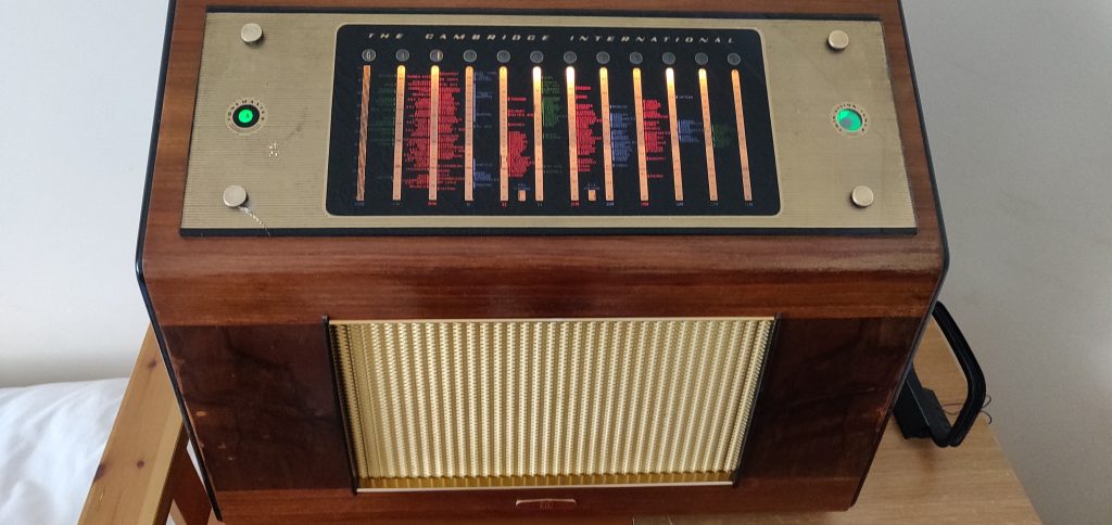
The remainder of the radio needed general cleaning up. The magic eye was dead so I had to go an find a working one to replace it. The tuning cord broken, so that was replaced as well as the tone indicator cord.
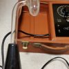
The power supply mains filter capacitors (there were two) replaced with modern X2 rated components.
The two output valves were replaced with new old stock EL41 equivalents, not because they were bad, but used on other projects! In fact, the only valve that did need replacing (apart from the magic eye) was the EBC41 amp/detector.
The finished assembled front view shown below.
I have the above PE 80 Radio. I need to know if there is someone, reputed who can restore it for me. I am located in Pune, India.
Please do inform me if you do.
Regards.
Firoz Bardi